


Home Site Map - Techniques - Automation and Data -
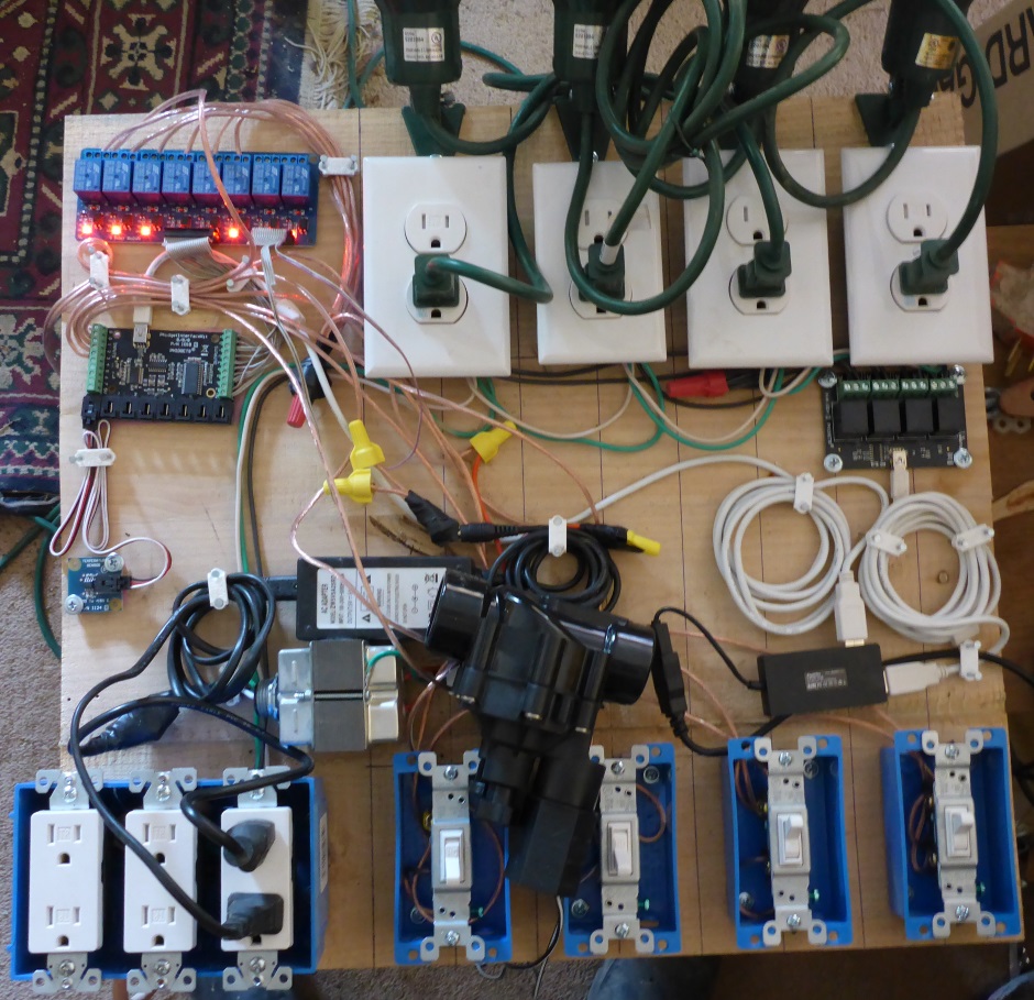
DIY Automation
![]() Home-brew way to control lights and heaters etc from your PC or tablet or
phone.
Home-brew way to control lights and heaters etc from your PC or tablet or
phone.
Sensor Board
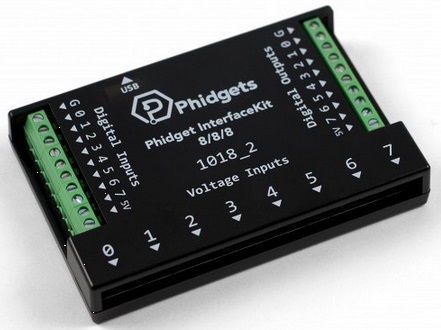
http://www.phidgets.com/products.php?category=0&product_id=1018_2 $80
Analog Inputs
The Analog Inputs are used to measure continuous quantities, such as temperature, humidity, position, pressure, etc. Phidgets offers a wide variety of sensors that can be plugged directly into the board using the cable included with the sensor. For more information about these inputs and their connectors, have a look at the Analog Input Primer. Sampling rates can be set at 1ms, 2ms, 4ms, 8ms and multiple of 8ms up to 1000ms.
Analog inputs are 5VDC (and no more). http://www.phidgets.com/docs/Analog_Input_Primer
Digital Inputs
The Digital Inputs have a Digital Input Hardware Filter to eliminate false triggering from electrical noise. They can be used to convey the state of devices such as push buttons, limit switches, relays, and logic levels.
There are pull-up resistors on the digital inputs so you don't need a 5VDC power supply for switches. Just connect the other end of the switches to ground (which is the first screw terminal). Digital inputs are 5VDC (but can handle +/-15VDC). Threshold is 4.2V. http://www.phidgets.com/docs/Digital_Input_Primer
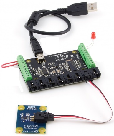
Digital Outputs
The Digital Outputs can be used to drive LEDs, solid state relays (such as the 3052 SSR Relay Board), transistors; in fact, anything that will accept a CMOS signal.
Digital outputs are 5VDC at 16mA. Provides 5V on the terminal block next to Digital Output 7.
User guide: http://www.phidgets.com/docs/1018_User_Guide
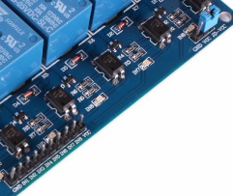
Relay Board
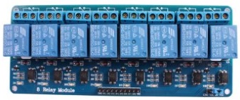
Adding this board to a the digital outputs of a Phidgets sensor board is a cost effective way of getting relay outputs.
http://www.amazon.com/gp/product/B00KTELP3I?psc=1&redirect=true&ref_=oh_aui_detailpage_o05_s00 $8.99
The relays are AC250V 10A ; DC30V 10A.
JD-VCC is used to power the relays. When the board is shipped, JD-VCC and VCC are jumpered together so that the VCC from the inputs side is used to power the coils on the relays. You will not want to try to use USB power to power the relays. Remove the jumper and use a separate 5VDC power supply brick for the relays. Connect the positive from the power supply to the JD-VCC pin and the negative to the ground pin.
Feed 5VDC directly from the Phidgets board for the logic circuitry (the pin next to digital output D7 on the Phidgets board) to the VCC pin on the relay board next to the control inputs.
These units energize when +5v is applied to VCC, then GND (+0v) is applied to the terminals. It's a bit counter-intuitive that +0v turns them on, and +5v turns them off, but that's how they work.
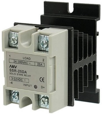
Solid State Relays
Rather than use mechanical relays it is better to use solid state relays. They are more reliable and can handle more current. You can connect them directly from the digital outputs on the Phidgets board.
$8.50
http://www.phidgets.com/docs/Solid_State_Relay_Primer
Note that this does not give you light dimmer functionality - only on and off. It also looks like it has a minimum load requirement.
http://www.anv.com.tw/pdf%5Ccs-SSR.pdf
Installing libraries
http://www.phidgets.com/docs/OS_-_Windows#Quick_Downloads http://www.phidgets.com/docs/Language_-_C_Sharp#Documentation http://www.phidgets.com/docs/1014_User_Guide
Air Temperature sensor
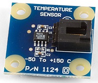
http://www.phidgets.com/products.php?category=35&product_id=1124_0 $15
Temperature sensor with a range of -30°C to +80°C with a typical error of ±0.75°C in the 0°C to 80°C range.
Make sure that Ratiometric mode is used.
Need to decide what temperature change amount causes the UI to be updated.
Waterproof Temperature sensor
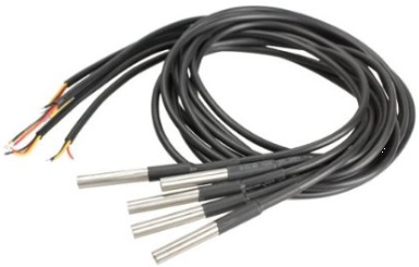
5V power. 5V use a 4.7k resistor between signal and VCC.
Output leads: Red (VCC), Yellow(DATA) , Black(GND)
(Possibly Red(VCC) Yellow(GND) Green(DATA)).
Data sheet:
http://datasheets.maximintegrated.com/en/ds/DS18B20.pdf
For
more information on how to use, see:
http://www.hacktronics.com/Tutorials/arduino-1-wire-tutorial.html
http://datasheets.maximintegrated.com/en/ds/DS18B20.pdf
http://www.atmel.com/Images/doc2579.pdf
http://mbed.org/users/snatch59/notebook/onewirecrc/
Can use the Microsoft OneWire library.
Light sensor

http://www.phidgets.com/products.php?category=6&product_id=1142_0 $7
The 1142 Light sensor can measure ambient light up to 1000 lux (roughly equivalent to the typical lighting in a studio, or the sky on an overcast day). Each sensor has been individually calibrated, and a label has been applied to the back of the board with a calibration value which can be used in your calculations to increase measurement accuracy. Some light sensors report drastically different values depending on the type of light being detected. The 1142 light sensor, however, only differs by a factor of 1.2 when measuring fluorescent light versus incandescent. If you need a larger measurement range, take a look at the 1143 – Light Sensor 70,000 lux.
Just plug it into an analog input on a sensor board. 5VDC comes down the sensor cable from the sensor board.
User guide: http://www.phidgets.com/docs/1142_User_Guide
Soil Moisture sensor
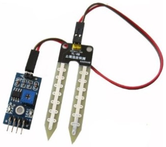
Module Output is high level when there is a soil moisture deficit.
Feed it 5VDC from a power supply.
Dual output mode: analog output more accurate.
Power
indicator (red) and digital switching output indicator (green).
Some people complained about corrosion. Either tin the probes with solder or use a stainless steel screw instead of the actual probe.
Do NOT apply current to the sensor continuously or it will send the metal ions from the plated sensor into the soil. You need to only power it up for the duration of the measurement. That means you probably need a relay on the 5VDC to it.
Pin Definition VCC 5V, GND, GND, DO Digital output interface (0 and 1), AO Analog output interface.
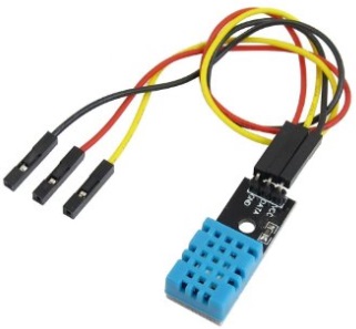
Humidity sensor
Magnetic sensor switch
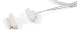
http://www.phidgets.com/products.php?category=32&product_id=3562_0 $2.50
Use a 5VDC power supply to one end and connect the other end to a digital input on the sensor board.
The 3562 magnetic contact switch is very small and is designed for surface mounted installations. The switch handles gaps of up to 12mm (1/2 inch) between the magnet and the switch. The switch will turn the digital input "on" when the magnet is within 12mm of the switch, and will turn "off" when the contact is broken by moving the magnet more than 13mm away.
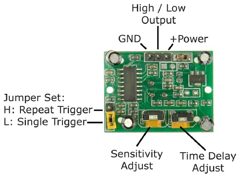
Motion sensor
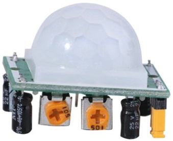
Use a 5VDC power supply and connect the output to a digital input on a sensor board.
Connection diagram is under the plastic dome. Take off the plastic cover and you can see where one side is GND (Ground), one will be 5V (power), and the middle is output (the low voltage signal).
Sensing range: less than 120 degree, within 7 meters.
Instructions: http://www.mpja.com/download/31227sc.pdf
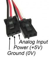
Analog sensor cable
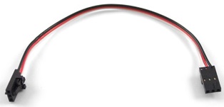
http://www.phidgets.com/products.php?product_id=3034 $1.50
This is just purchased to get the right connector for wiring up your own analog sensors.
Stepper motor controller
http://www.phidgets.com/products.php?product_id=1067 $95
Mini-PC
http://liliputing.com/tag/mini-pc
Prototype Interface Board