


Home Site Map - Techniques - Plot Infrastructure -
Sewage System - Types Of Systems
![]() There are various system designs ranging from moderate cost to
expensive.
There are various system designs ranging from moderate cost to
expensive.
Types of septic system
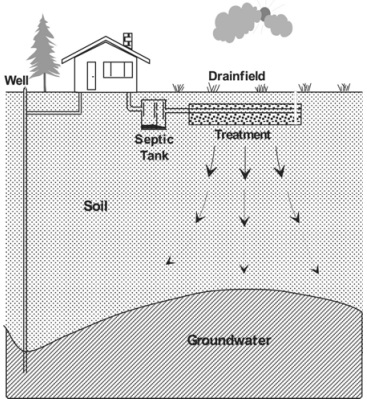
Before going further it is worth looking at some general info on how septic systems are designed. Here is the simplest gravity feed type...
The system type you need depends on the depth of permeable soil found on your site. Tests will need to be performed to determine this. You may need the test done in multiple places on your plot to try to find a place with the greatest soil depth. If you can find a place with a good soil depth (greater than 4 feet) then the septic system will cost you a lot less than if you have a lesser soil depth.
Gravity drainfields
As the name implies gravity drainfields work by letting gravity drain the effluent from the septic tank into a series of trenches. This means that a gravity drainfield area must be below the draining level of the septic tank.
A gravity drainfield consists of a septic tank which flows effluent by gravity to a distribution box (D-box) (the second compartment of a dual chamber septic tank). One or more connections to this D-box drain into trenches typically filled with gravel. Only a small part of the drainfield is used at any one time. It requires a minimum of 48 inches of permeable soil above a restrictive layer to be used on new construction. It has the least amount of maintenance required of any system type, but requires the greatest soil depth in order to provide adequate treatment of the effluent. My soil was nothing like good enough to allow me to use a gravity system.
Gravity with Pump
If you have good soil (48 inches of permeable soil above a restrictive layer) but the drainfield is higher on the land than the septic tank then a pump tank is necessary and it is called a "gravity with pump" system.
The drainfield is dosed which permits intermittent resting of the drainfield between doses. Additional maintenance to the pump tank and float switches are necessary.
Pressure distribution drainfields
Pressure distribution systems are usually installed when there is less than optimal soil depth available for complete treatment of the effluent by a gravity system (or gravity with pump system). Pressure distribution systems always have a pump and therefore they dose the drainfield with effluent and then let it rest until the pump tank accumulates enough effluent from the household for another dose. In addition a series of pressurized lines from the pump tank to the drainfield, it makes sure the entire drainfield receives effluent at the same time.
It requires at least 30-36 inches of permeable soil above a restrictive layer to be used on new construction. Maintenance is required to assure the orifices do not plug over time.
Sand filter system
When there is minimal soil available for treatment, a sand filter system is sometimes used. This consists of a sand containment vessel between the pump tank and the pressurized drainfield. The sand acts to treat the effluent before it enters the shallow soils on site. This effectively makes up for the lack of soil depth.
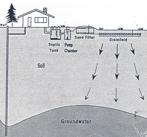
The sand filter typically has a pump tank inside it that gives pressurized doses to the drainfield.

It consists of sand placed in a watertight box built into the soil. Effluent is spread evenly over the surface of the sand via a pressurized network. The sand layer treats the effluent and the effluent is collected in the bottom of the filter box from which it is then pumped to a drainfield. The drainfield is a pressure distribution system, which finishes the treatment process and then disposes of the wastewater. It requires at least 18 inches of permeable soil above a restrictive layer to be used on new construction. The complexity of this system and the situations in which it is used requires periodic maintenance and proper operation to assure continued performance standards be met over time. If you have 24" of permeable soil and a suitable slope then you might be able to use a gravity feed from the sand filter to the drainfield.
Mound system
Another system that can be used when a site has inadequate soil depth is a mound. A mound is a drainfield raised above the natural soil surface with a specific sand fill material. Within the sand fill is a gravel bed with a network of pressurized pipes. Septic tank effluent is pumped through the pipes in controlled doses to insure uniform distribution throughout the bed. Treatment of the effluent occurs as it moves through the sand and into the natural soil. Drainage around the mound site is critical if the system is to function properly. On sloping sites the downslope area below the mound must remain protected.
This diagram shows a sub-surface mound...
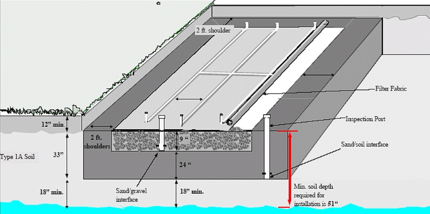
A treatment-based system consisting of pressurized lines lying in a sand bed mounded above the original soil surface. Requires at least 18 inches of permeable soil above a restrictive layer to be used on new construction. This system type has allowed construction on sites previously thought unsuitable due to lack of soil depth. The complexity of this system and the situations in which it is used requires periodic maintenance and proper operation to assure continued performance standards be met over time.
Sand filter + Mound
If you only have 12" of permeable soil then you may need to use both a Sand Filter and a Mound.
Septic system components
Septic tank
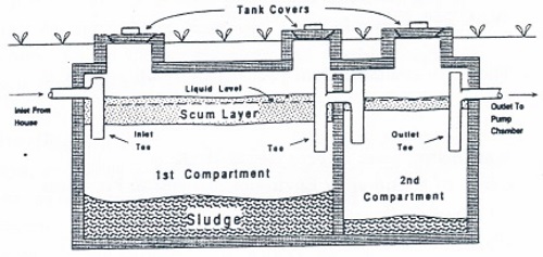
The typical septic tank is a large buried rectangular or cylindrical container made of concrete, fiberglass, or polyethylene. Wastewater from your toilet, bath, kitchen, laundry, etc. flows into the tank. Heavy solids settle to the bottom where bacterial action partially decomposes them to digested sludge and gases. Most of the lighter solids, such as fats and grease, rise to the top to form a scum layer.
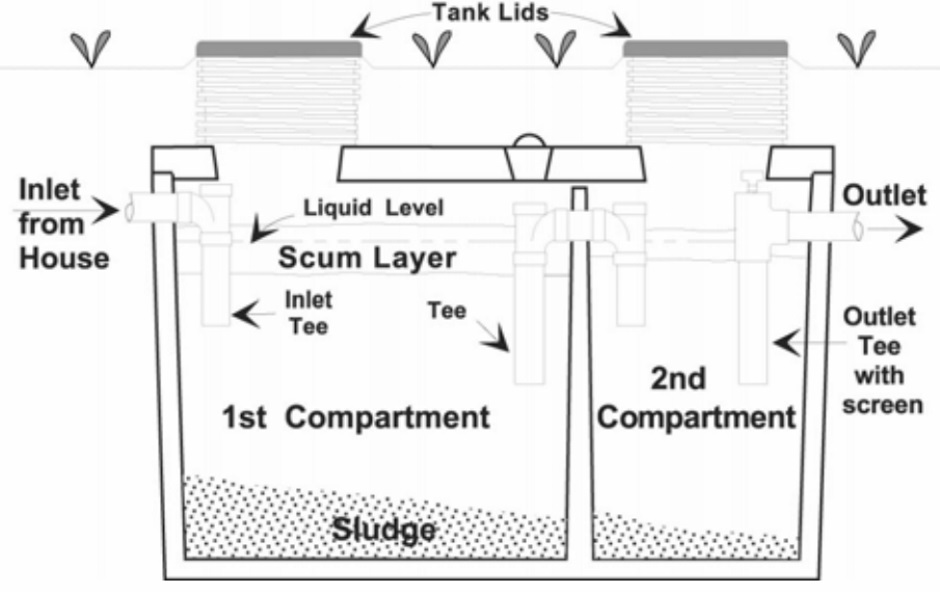
Septic tanks may have one or two compartments, but in my area the use of a dual compartment tank is mandatory. Two compartment tanks do a better job of settling solids and are required for new systems. Tees or baffles are provided at the tank's inlet and outlet pipes. The inlet tee slows the incoming waste and reduces the disturbance of the settled sludge. The outlet tee keeps the solids or scum in the tank. All tanks should have accessible covers for checking the condition of the baffles and for pumping both compartments. If risers extend from the tank to or above the ground surface, they should be secure to prevent someone accidentally falling into the tank. Solids that are not decomposed remain in the septic tank. If not removed by periodic pumping, solids will accumulate until they eventually overflow into the drainfield (which will wreck the drainfield). Most septic tanks need to be pumped every 3 to 5 years, depending on the tank size and the amount and type of solids entering the tank. Getting it pumped costs money so I prefer to use as large a septic tank as possible (1750 gallons).
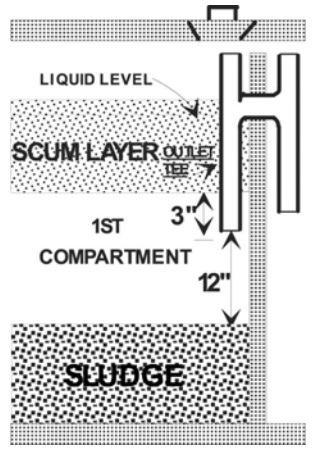
The septic tank should be pumped when:
1) The bottom of the scum layer is within 3 inches of the bottom of the outlet tee or baffle, or
2) The top of the sludge layer is within 12 inches of the bottom of the outlet fitting.
The wastewater leaving the septic tank is a liquid called effluent. It has been partially treated but still contains disease-causing bacteria and other pollutants. Discharging effluent onto the ground's surface or into surface and ground water is against the law in most jurisdictions.
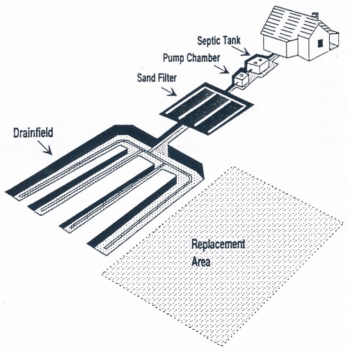
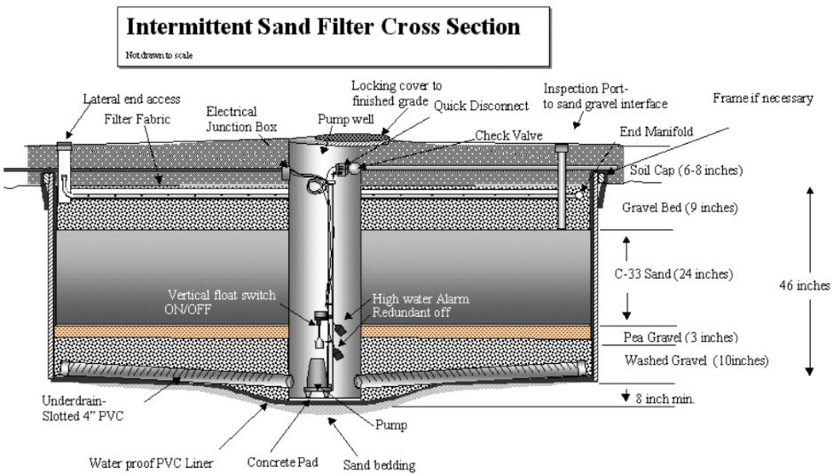
Sand Filter
The sand filter itself is a concrete or PVC-lined box filled with a specific sand material. A network of pressurized lines is placed in a gravel-filled bed on top of the sand. The septic tank effluent is pumped through the pipes in controlled doses to insure uniform distribution. As the effluent trickles down through the sand it is treated. A gravel underdrain collects and moves the treated wastewater to either a second pump chamber for discharge into a pressurized drainfield or (less likely) the filter can sometimes drain into a gravity flow drainfield. The second pump chamber is commonly located within the sand filter.
Drainfield
A drainfield consists of a network of 4 inch diameter perforated pipes laid in gravel-filled trenches (2-3 feet wide) in natural undisturbed soil. The bottom of the trench needs to be 3 feet above any restrictive layer, such as a hardpan, or water table. The soil between the bottom of the trench and the hardpan or water table is used in the final treatment of the septic tank effluent. The soil below the drainlines filters effluent as it passes through the pore spaces. Chemical and biological processes treat the effluent as it percolates down through the soil. The treatment process cleans the effluent before it reaches the groundwater. This works best when the soil is somewhat dry, permeable, contains adequate amounts of oxygen, and there is enough soil depth to complete the cleaning process. The size of the drainfield depends on the estimated daily wastewater flow and soil conditions. The number of bedrooms and soil type determines the total number of square feet of drainfield area that is needed.
General info on septic systems
Much of the above info comes from the excellent info published by the King County Health Dept at http://www.doh.wa.gov/Portals/1/Documents/Pubs/337-086.pdf
Lots of good information also at http://www.kingcounty.gov/healthservices/health/ehs/wastewater/owners/types.aspx
http://www.kingcounty.gov/healthservices/health/ehs/wastewater/owners/works.aspx
Also see http://www.doh.wa.gov/CommunityandEnvironment/WastewaterManagement/FormsPublications#Tanks
http://www.doh.wa.gov/Portals/1/Documents/Pubs/337-083.pdf
http://www.doh.wa.gov/Portals/1/Documents/Pubs/337-003.pdf