


Home Site Map - Techniques - Plumbing -
Plumbing Drain Waste Vent
![]() Lots of practical advice on how to design and implement your DWV
configurations.
Lots of practical advice on how to design and implement your DWV
configurations.
My DWV configurations
These are the DWV configurations that I have standardized on and use.
I avoid wet venting because it is not practical to meet all the ever increasing rules associated with wet venting without making the vertical height not fit within the available floor thickness.
Bathroom
Run the toilet line from the 4" vertical sewer stack using 3" pipe
where it typically ties into the stack using a 4-4-3-3-Double-Wye-45 (or
a 4-4-3-Wye-45, or a 4-2-2-Sanitary-Tee, but NEVER a
4-4-3-3-Double-Sanitary-Tee (Sanitary-Tees are not needed as it is not a
vent, and double Sanitary-Tees of this port size ratio are illegal)).
In the 3" pipe to the toilet area put in
two upward facing 3-3-2-Wyes
for the floor drain and the bath or shower. Also add a 3x3x2-Wye
for the sink. Under where
the toilet will be, fit a long sweep 3" 90 degree bend upwards.
After the bend put an upward facing 3-3-2-Wye-45. Continue the 3"
pipe upwards to the toilet flange at the required toilet height.
For the sink, use a 3x3x2-Wye followed by a 2x2-45-bend and connect 2" horizontal pipe
(slightly upward sloping) to the wall. At the wall do a 90
degree bend and continue the 2" pipe up the wall to 5 foot above floor
height where it will connect with the horizontal vent pipe for that
building level.
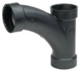
(Relative to the picture shown below, it is often best to use an offset toilet floor flange.)
Onto the 3x3x2-Wye-45s fit Sanitary-Tees, 2x2x2 for a floor drain or shower and 2x2x1.5 for a bath. Into the top of the Sanitary-Tees goes a 2x2-90-bend and these vent pipes go to the wall and then upwards.
I have 8" between the top side of the ceiling drywall and the bottom of the concrete floor beams. This equates to 4" for the outside diameter of a 3" pipe plus 4" of rise for the slope. A 4" rise allows for 16 feet of pipe length in the ceiling from the stack (1/4" per foot). This is plenty, particularly given that some of the piping is in the wall of the building level below and so does not count against ceiling distance.
Isolated sink
This refers to the case where there is a fixture all by itself. It might be a sink, or a drinking fountain, or some other fixture type. Sometimes it is just more convenient for pipe routing to consider a fixture separate even if it is physically close to other fixtures.
Put a vertical 2" pipe in the wall behind the fixture. At the
bottom of the wall the 2" pipe will have a long turn 90 degree bend
and continue in a slightly downward slope until it eventually finds
its way to a 4" sewer stack, where it will typically connect using a
4-4-2-Wye-45 or pickup on a convenient horizontal 3" pipe using a
4-4-3-Wye.
In the vertical 2" pipe behind the fixture, half an
inch below level with where the arm from the sink's P-trap will be
in the vertical 2" pipe you put in a 2-2-1.5 Sanitary Tee.
There
will be other fixtures somewhere else on that building level and
there will therefore be an upside-down vent Wye and probably a 2"
horizontal vent pipe. Out of the
top of the tee for the sink, you continue to a height of 5 feet up
the wall and then route to the vent pipe.
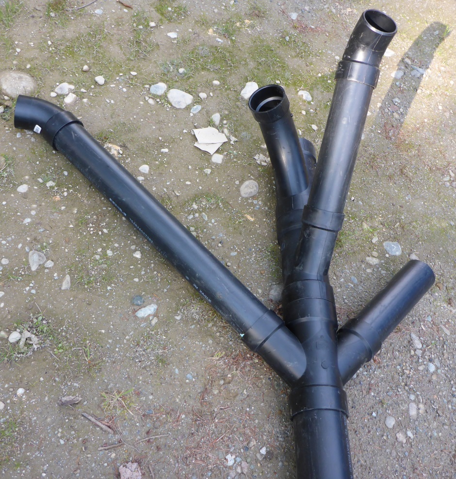
DWV scheme I use
For each floor for each 4" stack it is possible to have one 3" branch come off at an arbitrary angle directly in the ceiling of the floor below and to have one or more other 3" branches that make use of the walls in the floor below to get them up to ceiling height.
The angled branch at the top uses a 4x4x3-Wye-45.

The other branches (underneath in the stack) use a 4x4x3-Wye, a length of 3" pipe, and a 3x3-45-bend.

If you need even more branches and those branches are 180 degrees from each other then you can use a 4x4x3x3-Double-Wye, a couple of lengths of 3" pipe, and a couple of 3x3-45-bends.
There is one situation (the north west stack) where I use all three variants, ie a 4x4x3x3-Double-Wye (one leg through the internal ICF wall and the other along the north wall), with a 4x4x3-Wye above (feeding south along the internal ICF wall), then a 4x4x3-Wye-45 above that (at floor height heading south west). The stacking order of the lower two takeoffs can be reversed if it works better with the walls.
The 3" branches take the simplest shortest path to the various toilets (or potential future toilets). Where possible use one 3" branch per toilet but it is allowed to put in a 3x3x3-Wye to horizontally branch off to a second toilet (max of two toilets on one 3" line).
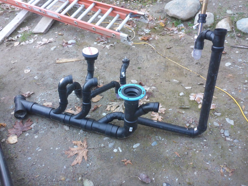
Here's a picture of the configuration I use in the north west stack...
DWV parts I use
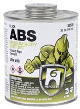
I have made the choice to use ABS pipe and fittings because I like how nice and sturdy ABS is. It is a little harder to work with that CPVC because it does not dry-fit easily and the glue sets very quickly, however with a little experience it all works well.
Purchasing details for the ABS parts I use are here .
ABS needs of course to be glued with ABS glue (not PVC glue).
Traps
The water trap under fixtures that prevents sewer gasses coming into the room is often called a P-trap (because it is shaped like a P facing downwards). The leg of the P refers to the fact that the pipe after the trap needs to be a (slightly downward sloping) horizontal pipe to the sewer stack. This allows proper venting and avoids the siphoning that can occur with the old (and now illegal) S type U bend that went vertically down after the trap.
Ideally traps should ideally be...
1) Made so you can retrieve objects, eg retrieving rings dropped down sinks or bath drains.
2) Be transparent so you can see any problems and see that they have not dried out.
3) Long and deep because it is less likely that they will dry out if left unused for a while.
Many of the P-traps typically used are horrible in that they leak. They are also a pain to remove and reconnect for cleaning. I prefer to use the type of U bend used in hair salons. They are designed to trap anything that falls into the sink and are easy to clean. You just unscrew the cap and pull out the strainer. Because they are transparent you can see if they are blocked and particularly in the case of a floor drain you can check to make sure the water in the U bend has not evaporated away. The only issue is that they are only available with a 1.5" size whereas showers and floor drains need 2".
 Purchasing info is here
.
Purchasing info is here
.
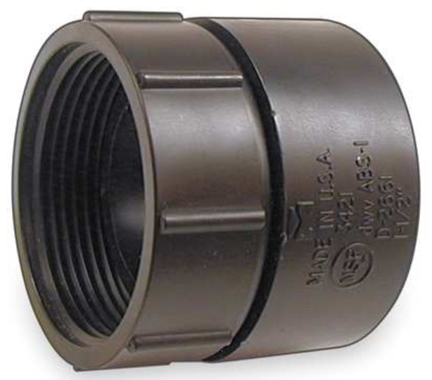
Except on the input side when directly under a sink, I attach the hair trap U bend (input and output) using swivel ABS connectors.
 Purchasing info is here
.
Purchasing info is here
.
Using the hair trap with the swivel connector and a 90 degree Female-male bend will result in a trap that is just less than 4" deep (and so is inside the 4" allowed by code).
Implement the 1.5" horizontal pipe (not more than 3'6" long) from the trap (using a swivel ABS connector) to the 2x2x1.5-Sanitary-Tee on the 2" ABS drain/vent pipe.
The drain waste pipe needs a cleanout at its highest end, but removable toilets and sinks with removable P-traps count as cleanouts.
For bath drains, shower drains, and floor drains it is ok to connect ABS pipe down through the floor to the trap.
Home-built 2" hair trap
Floor drains and dedicated shower drains need to be 2" diameter and the piping from them must not be less than that. This means that the trap cannot be 1.5". This means that you cannot use the transparent traps.
Rather than use a 2" trap a better bet is to make a 2" trap from ABS parts and include a cleanout at the end much like a hair trap does. Use a 2x2x2-Wye, a 2x2-45-bend, two 2x2-90-bend, and a 2in-cleanout-plug. For a filter you can add some crumbled wire mesh or some course filter mat. (Need to make sure the water height is not more than 4".)
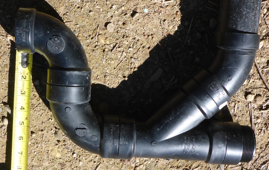
As you can see from the tape measure in the photo, the water depth in the trap is 4" and so is allowed.
Floor drains
The building code regarding whether or not floor drains are required is a bit unclear and varies with jurisdiction.
Certainly it is not good to have a floor drain in the basement concrete slab. If the building inspector insists then implement a raised floor in the basement bathroom (it will have to be several feet high to be able to flow out to the 4" house drain that is a foot and a half up the wall).
I use floor drains in all bathrooms on the main and bedroom levels and I am very much in favor of having them. These bathrooms are full wet rooms.
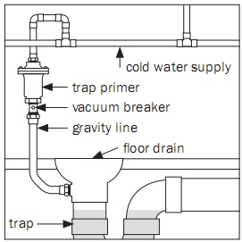
Floor drain trap priming
Traps for in particular floor drains can dry out because they are not frequently used and this will lead to sewer gasses coming into the room. A trap primer aims to ensure the water in the trap is always present.
Plumbing code on this varies depending on the jurisdiction, but it is the case that trap primers are now mandatory for all floor drains in most geographical regions.
Trap seal primers should be installed at least 12" above the floor drain traps for every 20 feet of distance to the drain to ensure that there is enough of a slope for the discharged water to flow to the traps.
Some floor drains have a small threaded hole that allows you to attach a 1/2" PEX pipe to feed it water...
 Purchasing info is here .
A complication is that the thread is a "female 5/8" compression". It is complicated to convert this to 1/2" PEX, but the details of how to do it are here .
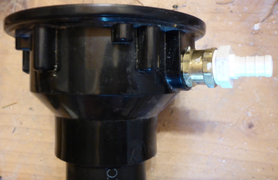
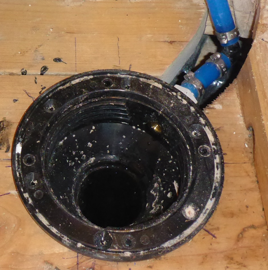
Even though the drain unit comes with a threaded side hole you still need to remember to drill it out to allow water in.
An adapter is needed to get from the "male 5/8" compression" thread on the drain unit to half inch PEX. The details of how to do it are here .
Water feed
Described below are two ways of providing feeding water to the drain. On balance I prefer the "Sink takeoff" method.
Sink take-off method
The simplest method is to use a take-off from a frequently used sink. This uses gray water from the sink to prime the drain U bend so it does not use any additional potable water. It will not automatically work when leaving the house unoccupied for a long vacation so you may need to get someone to visit the house while you are away to turn on the tap to the sink
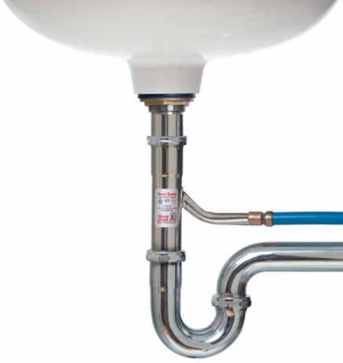
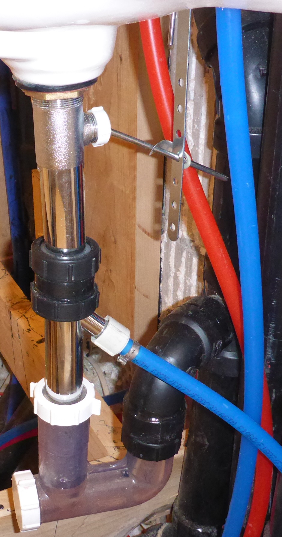
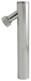
On the end of the 1-1/4" sink drain pipe (that typically has the plug popup mechanism) you fit a 1-1/2" take-off assembly. This connects to the sink drain pipe using an ABS male screw piece and an ABS 1-1/4 slip ring piece.
(With the transition from 1-1/4" to 1-1/2" you need to check that it really is managing to get water to the drain under normal sink usage scenarios).
 Purchasing details are here
.
Purchasing details are here
.
You remove the chrome nut and fit a commonly available plastic half inch NPT to half inch PEX pipe adapter (the thread is not exactly right but it will go on ok).
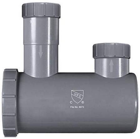
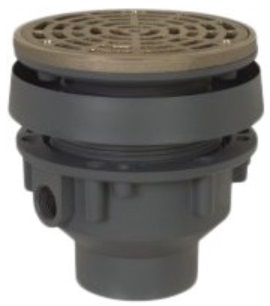
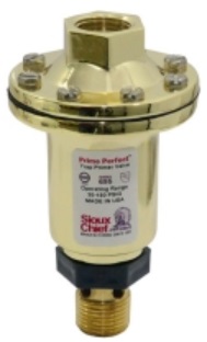
Potable water valve method
It can be done using a device pictured below that is fed from a potable water feed and injects water into the trap whenever it senses pressure changes in the water feed. This is not that great because the well house pressure cycles up and down and will cause the valve to operate each time. It might also look like you have a water leak when looking at the wellhouse water meter. When leaving the house unattended while on long vacation (assuming the wellhouse is left in operation) it will work because the pressure in the wellhouse will gradually reduce and then the wellhouse pump will kick in and so will the trap primer valve.
 Purchasing details are
here .
Purchasing details are
here .
Feed the primer unit using 1/2" PEX pipe from a potable water manifold output. Need to attach the pipe (1/2" PEX) to the drain. Can be in the ABS pipe between the drain and the trap. One primer can potentially feed multiple drains if the drains are not too far apart.
They are installed on the potable cold water supply line, and react to water flowing in the line to trigger, typically by pressure drop. Once a triggering event occurs, the primer will release water that is piped to a trap primer connector on or near the “P” trap being maintained.
Many local codes require the use of an air gap fitting underneath the trap seal primer. The purpose of an air gap fitting is to provide a vertical space that is twice the diameter of the water supply connection in order to ensure positive protection against backflow. The pictured device has an air gap built-in.
Pressure drop activated trap seal primers are typically manufactured out of brass. They are made with a 1/2” M.I.P. inlet connection and a 1/2” F.I.P. outlet connection. They have an interior cartridge that seals when the line pressure is in a static state. When the line pressure drops slightly (caused by the flushing of a toilet, opening of a faucet, or any draw of water from the water supply line within a close distance to the primer) the interior cartridge will rise due to the pressure differential within the primer and a metered amount of water is discharged under pressure into the plumbing line connected to the floor drain trap.
Hybrid method
Use the sink drain takeoff method, but you could rig up a potable water valve that feeds water into the various sinks while on long vacation. This is not necessary to meet building code.
Using sink drain for disposing of other water
There needs to be a drain from HRV (Heat Recovery Ventilation) units and an there should ideally be a drain pan under a hot water boiler. These sources of water need to get to a drain via an air gap. You don't want a separate trap for these because the trap will probably dry out and then you will get sewer gasses into the room. You may not want a pipe outlet above a sink because that will annoy users of the sink. You could decide to route a small pipe out through the wall. Another alternative is to feed the water via a 1/2" PEX pipe into the drain stem from a sink just above the sink's trap. This topic is not addressed by plumbing building code and as such might be something questioned by the plumbing inspector, but I think it will probably be allowed. Feeding it in can be done using an ABS fitting with a side port (assuming it is nicely hidden in a cabinet). The PEX pipe should come from above so that no sink water can flow down it.
Fitting ABS and PVC
Dry fit first. Always mark with a felt pen or scratch to indicate full depth into the join and angle of fitting.
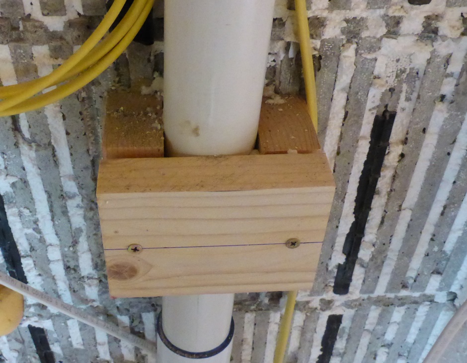
Fixing DWV piping
This picture (which is of a 2" PVC pipe rather than the ABS used for the DWV piping) shows a good way to secure the piping. Wood blocks are glued using PL-Premium to the concrete on both sides and then when the glue has dried you can screw on a top piece of wood. The thickness of the top piece is cut on a table saw such that the final height matches the distance to the back of the drywall.
Sewer stacks and pipe from house
In the basement, much of the plumbing design is influenced by a desire to avoid piercings through the slab. This is to avoid the possibility of ground water getting into the basement. Toilets are wall mounted with the waste exit from the toilet being horizontal (slightly sloping) into and along the wall.
It is best for the sewer pipe to come through the wall just above slab height rather than come through the slab. I have also decided to route the radon vent pipe under the footing rather than have it come through the slab.
Note that it is against plumbing code to use Double Sanitary Tees with 3" side-ports on a 4" stack. Instead use a 4x4x3x3-Double-Wye with two 3x3-45-bend-Female-Male pieces.
DWV implementation tips and tricks
DWV plumbing needs to be done before you put physical obstructions in the way, eg countertops, flooring, etc. The hardest thing about implementing DWV plumbing is not having enough physical space.
Pipes should either (slightly sloped) horizontal or vertical or 45 degrees.
Wyes should have the tail come out either vertically or horizontally (unless the pipe from the tail will go via a 45 and then go parallel to the mother pipe. You need to get the tail to vertical or right angle horizontal as soon as possible (typically via a 45-Male-Female).
When two 2" vent pipes run up the wall and will need to combine to become one vertical pipe then the pipes need to be 4" apart. They combine using an upside-down 2" Wye with a 45-Male-Female.
Cut yourself a set of pipe lengths in 2" and 1.5" pipe. Make between 2" and 12" in 1" increments.
When dry fitting the ABS together use some 1" long pipe sections to join parts that are butt to butt connected. These will eventually get replaced with 1.5" lengths but dry fitting with 1" lengths is easier.
When gluing, use ABS glue sparingly on the female end of the fitting and liberally on the male part. This is to avoid getting a big blob of glue inside the pipe.
When possible, cut the pipe to length with a chop saw so you get a true right angle cut.
Build yourself a prototype bathroom configuration and leave it in the yard so you can look at it prior to doing the actual implementation in the real bathroom.
After dry fitting (that will have used slightly shorter pipe sections), measure the length between parts and then add two take-off lengths for inside the parts.
After dry fitting, build subassemblies of parts that you are confident about. Dry fit the subassemblies together to check everything is good. If things are bad then all you have lost is the cost of the parts in that subassembly. What must be avoided is screwing up bits you cannot change such as the main stack. Where you are uncertain of an angle or a length then this should be a dry join between subassemblies rather than a glued part of a subassembly.
When gluing a sub-assembly, use about 9" lengths of pipe in the hubs
to help you see that everything is square.